About ten years ago I was given ISA graphics cards from 286 ... 486 cars. Video cards have been tested and since then gathering dust in a box. A couple of years ago, I had an idea, but would it be possible to connect such a video card to a microcontroller? That's what I will tell in the article.
To connect an old ISA-video card is enough 8-bit data bus and 20-bit address bus. Microcontrollers I love the AVR families for their simplicity, so I took Atmega16. But you can take any convenient for you - in this case, the same stm32 legs will be exactly enough without external strapping. But Atmega16 legs on all these tires is not enough, so the address bus was collected on three more Soviet parallel registers (I have a large supply of them) K588IR1. The microcontroller in turn sets part of the address in these three registers. More and is not required.
On the ISA-connector, the outputs of this circuit must be connected as follows:
+5,
+12,
GND,
REFRESH (drawn to + 5V through a resistor),
A0-A19,
D0-D7,
RESET,
MEMW,
MEMR,
Iow
IOR,
ALE,
Rdy,
AEN (connects to GND).
In the picture in red, I marked the required ISA connector pins.
For some video cards, you need to connect -5 V and -12 V (you will have to get them from somewhere - for example, from TracoPower sources) and the OSC signal (14.318 MHz) - it can be generated with a simple K155LN1 generator. Other video cards do not require these lines. Then how lucky. In general, if on the video card the corresponding leg on the ISA is hanging in the air, you just can not connect it. Keep in mind that the video card's consumption on the + 5V line is quite substantial - if you use something like the LM7805 to power, be sure to put it on the radiator (preferably with a fan).
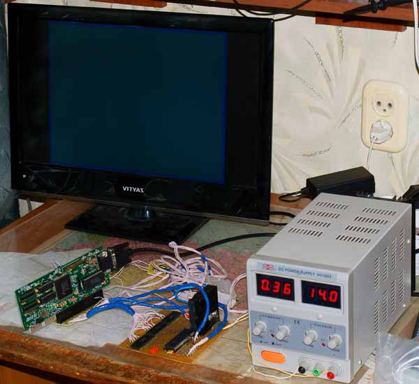
Personally, my assembled construction looks like this:
It remains the case for small - somehow initialize the video card and start working with it. There are similar projects on the Internet - I found one (
link ), from where I took the Trident 9000i video card initialization code. In the same program from the Internet there is also an initialization code for the Trident9000C, but in the comments it is indicated that it does not work. I checked. It really does not work - the garbage on the screen and the video card does not respond to writing data to RAM.
Video of work (the picture was transmitted via SPI to Atmega16 (as you can see, these lines are left free on the diagram) via the computer's LPT port):
(I made a reservation in the video - 320x200 mode, not 320x240)
Combining this module with an optical mouse (
an article about using a mouse sensor ), I got this:
If you want to run any available ISA video card, then for this you should find the BIOS of the required video card (say,
here ) on the Internet and use the IDA to disassemble it. There is the usual X86 code. It only begins with a non-zero address - there is a signature (2 bytes) and a checksum (1 byte). So, start with the 3rd byte. And successively find out which ports need to be recorded for the card to work. Frankly, I did not have enough patience to understand what is wrong with the Trident9000C.
A module was written to work with the ISA bus:
Module for working with the ISA bus Trident 9000i video card is initialized like this:
Trident 9000i video card initialization I also ran the OAK OTI077 video card (until I accidentally filed a 12 V on it and it did not burn):
Initializing video card OAK OTI077 By the way, are there any VGA adapter register specialists? I see strange things in the video mode change code when initializing a video card:
Here, in general, there is nothing special. Writing to the registers of the attribute controller is done in 2 steps: first write the register number, and then the data. To always start by writing down the number, read ISR1 (from 0x03DA) - so it’s done.
But here's what's strange. Attribute controller has no register 0x20! He has the last register 0x14. And even if such a register would have been, why is there no record of the value? There must be two entries in the port. And here she is alone. I searched the Internet and found that for some reason (I didn’t find it in the books) you can write, say, in the 0x10 register the value 0x20 at a time simply by combining the bits: System_Out8 (ATTRCON_ADDR, 0x10 | 0x20); Then the specified entry writes 0x20 to register 0x00? But why does this work? And is that so? This is interesting to me, that's why - the thing is, sometimes the color falls off after initialization. The palette is simply not set. It can be seen that it is changing, but the colors are not what they should be. If the initialization is done again, then everything is restored. At what stage it happens is not clear. Experimentally, I found out that with high probability, this is just the installation of the video mode. But that's what's wrong there, I do not understand.
→
Link to PCB archive
→
Link to archive with firmware