
One of the most difficult tasks in computer-aided design systems is
filletting when modeling objects of complex shapes. For the construction of fillets, as well as for all geometry in CAD, the geometric core is responsible.
From the point of view of the kernel developer, it is impossible to cover all variants of fillets because of their infinite variety. Our mathematicians are constantly adding new special cases to the C3D core, and have recently done a rounding of three faces (or full rounding).
What is its complexity and how the algorithm works, says Anna Ladilova, mathematician and programmer at C3D Labs.
What is full rounding?
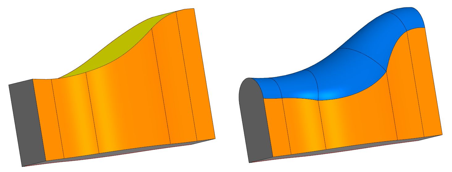
Suppose we have a body with three chains of faces - central (upper) and side (right and left). It is required to replace the central face with a fillet surface that would smoothly fit into adjacent side faces. This new surface will be full rounding. In general, it has a variable radius that is automatically detected.
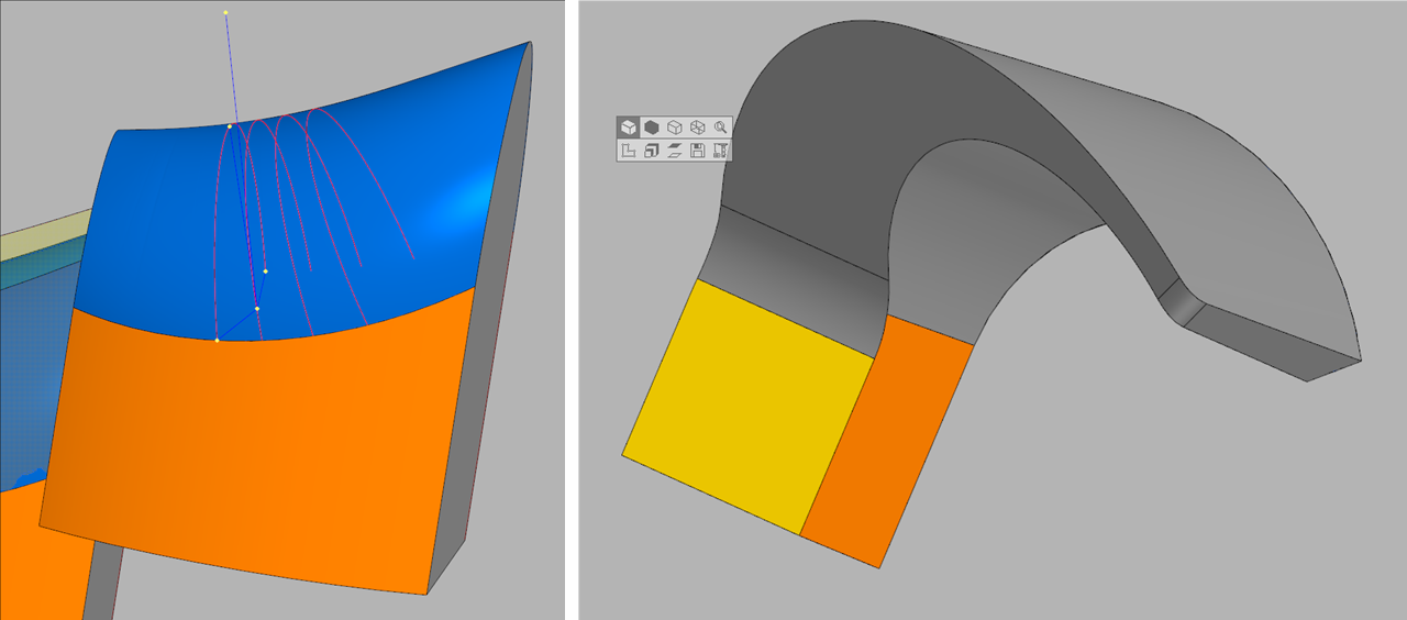
In many well-known CAD systems, the full-round fillet operation is implemented, but its mathematics is not disclosed.
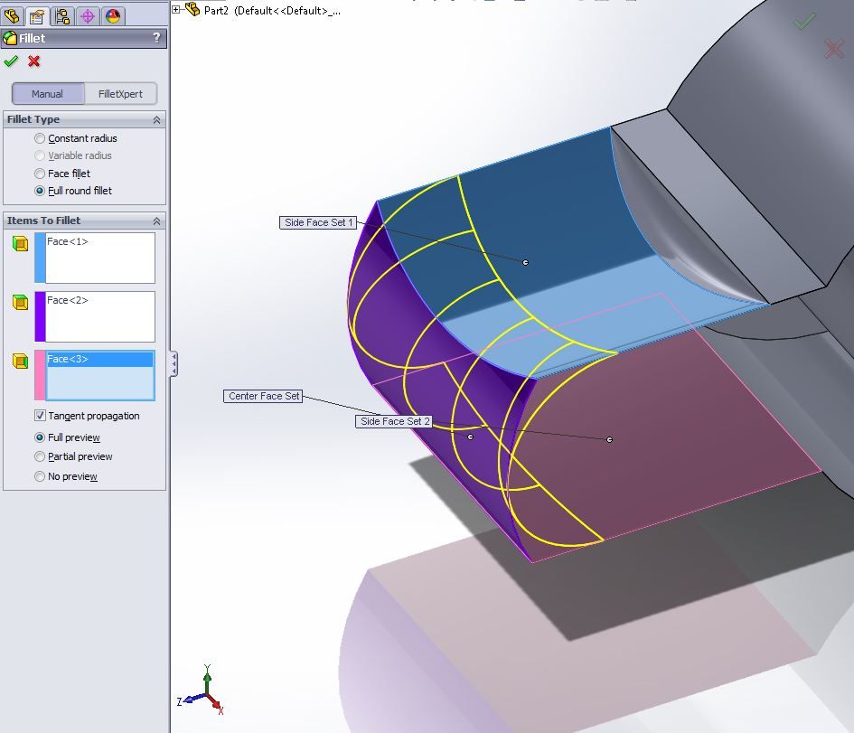 Operation Full round fillet in Solidworks
Therefore, we developed our own algorithm. And it differs from the algorithms of other developers.
The operations, although they are called the same, lead to slightly different results. This suggests that SolidWorks gives a different definition for rounding three faces.
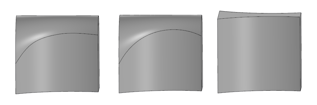 On the right is the original model, in the center is full rounding in SolidWorks, on the left is in C3D.
Full rounding algorithm
The task of constructing any kind of fillets includes several stages:
- Break the given chain into elementary components (for rounding three faces it is exactly three faces: left, right and center).
- Consistently arrange elementary components.
- Build a fillet surface for each elementary component.
- Stitch adjacent fillet surfaces with ribs.
- To process the end sections of the fillet chain, i.e., correctly connect them with the modified body.
The key point in this procedure is the third step: to build a fillet surface for three given faces.
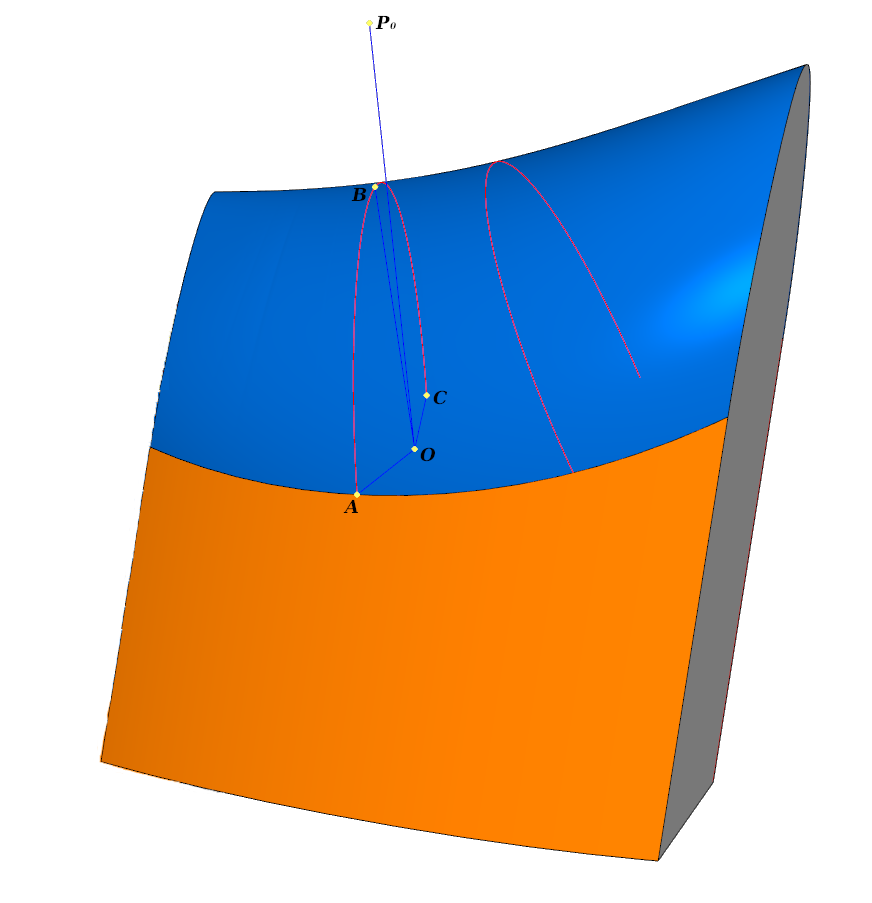
To construct the desired surface, it is initially necessary to determine the curves by which the fillet touches each of the three faces. In the general case, these curves can only be constructed as splines passing through known points that are calculated in advance.
Consider how you can calculate a triple of points - one on each spline.
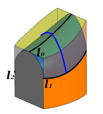 Elemental processing. The fillet touches each of the three faces along the curves l 0 ; l 1 ; l 2 . The blue line shows the cross section
In each cross section
:
- - calculated automatically
- orthogonal to the tangent planes of the surfaces at the corresponding points
- 0 - anchor point, lies in the plane .
We define the initial surfaces of the central, left, and right faces by radius vectors in a certain domain of definition. Let the lateral surfaces be defined by radius vectors
one and
2 and the central one
0 . We introduce a positive numerical parameter
.
Denote by
0 ,
one ,
2 single normals to the corresponding surfaces, directed "inward".
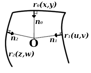 Cross "section" when constructing a fillet
We require that the ends of these normals stretched in
times, hit one point - point
.
In terms of differential geometry, our requirements can be formulated by a system of seven equations with seven parameters:
0 =
one ,
0 =
2 ,
(
0 -
0 one -
0 2 -
0 ) =
,
Where
- - variable radius
- 0 - anchor point
- - variables from the parameter definition area.
Using algorithms of numerical methods (for example, Newton's method), we find a solution to this system:
0 0 0 0 0 0 0 .
The solution defines touch points with surfaces:
- 0 ( 0 0 )
- 1 ( 0 0 )
- 2 ( 0 0 )
as well as radius
0 .
Running through a set of points
0 , we get sets of triples of tangent points with surfaces from which you can restore “touch curves”
0 1 2 as Hermite splines passing through calculated points.
Domain [
min max ] all the curves are the same, and the parameter
i correspond to a point
0i 1i 2i . Further, these curves are used to calculate the desired fillet cross-section.
We fix some parameter
and calculate the points for it:
- 0
- one
- 2 .
We construct a spline curve passing through these points and normal vectors orthogonal to them
0 ,
one ,
2 respectively.
If the problem statement is slightly changed and the curve is searched for by given points and tangent vectors at these points, then the methods by which such a spline can be implemented can be found, for example, in Nikolai Golovanov's book “Geometric Modeling”.
The book describes in detail the methods of rounding the edges of the body, in particular, it is shown that the cross-section of the rounding can be realized as a NURBS curve defined by three points. If three faces are rounded, a similar curve will be determined by five points.
So for each parameter
we can define a set of points for building NURBS, and therefore, define each point of the cross-section of the fillet surface. Thus, the problem of surface construction is completely solved.
In the description of this part of the algorithm, a small question remained - how to "choose" a set of points
0 corresponding to the cross-section through which it will be easy to restore the “touch curves”
0 1 2 ?
It seems reasonable to take them with some pre-selected curve. We will not go into the details of constructing this curve, we only note that it should be smooth, without self-intersections and “average” the chains of edges bounding the central face on the left and on the right.
 Left, cross-sectional, point-dependent 0 .
On the right, figures can be quite complex, so choosing the “auxiliary” curve correctly is a separate task.Now that we are able to build fillet surfaces for the simplest elementary cases, we can move on to a more complex problem: to construct a surface for a chain of faces.
The main problem here is to “sew” adjacent surfaces in a smooth manner. This is the fourth step of the algorithm.
The difficulty lies precisely in the smoothness of crosslinking, since the surfaces are built with different initial data. To ensure smoothness, one has to resort to various tricks: change the direction and length of the vectors of derivatives in the longitudinal direction at a certain distance from the boundary, change the values of the derivatives of weight functions at the boundaries, etc. The results are visible in the figure: the smoother zebra lines correspond to a smoother surface.

 Above is a model without a smoothing algorithm. Below - after applying the algorithm.
Total
As a result of our research, the C3D geometric core is able to construct a fillet cross-section, support curves, fillet of three faces; knows how to smooth the surface by choosing a parameterization; partially knows how to smoothly join adjacent fillet surfaces.

Author - Anna Ladilova, Ph.D., mathematician / programmer C3D Labs