こんにちは、同僚の皆さん。 この記事は、ポスト
habrahabr.ru/post/178103で開始されたトピックの続きです。
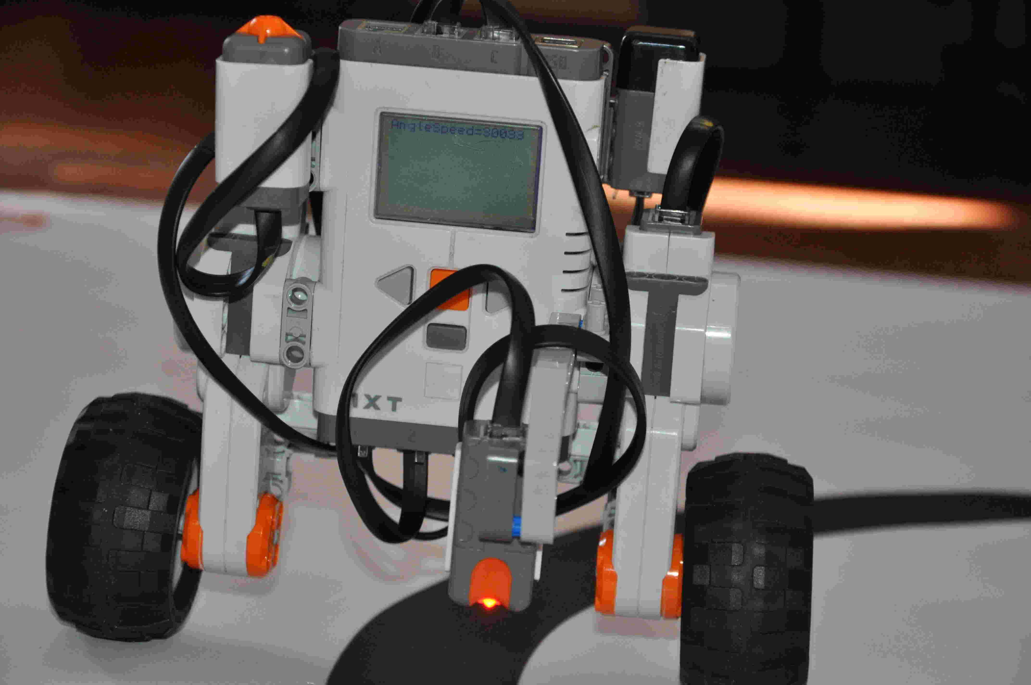
レゴエンジンの構造定数の値が既にある時点から続行し、ロボットの設計と計算に進むことができます。 プロトタイプとして、セグウェイについて詳しく見てみましょう。 これは、自動制御の理論の最も重要なタスクの1つです。 このメカニズムの設計を示します。
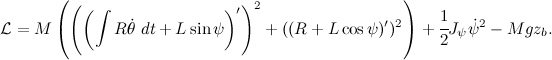
まず、ロボットの数学モデルの導出について説明します。 次のように一般化座標を選択します。
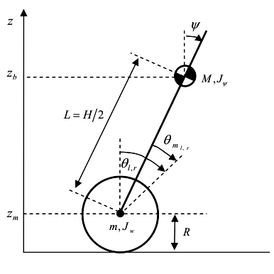
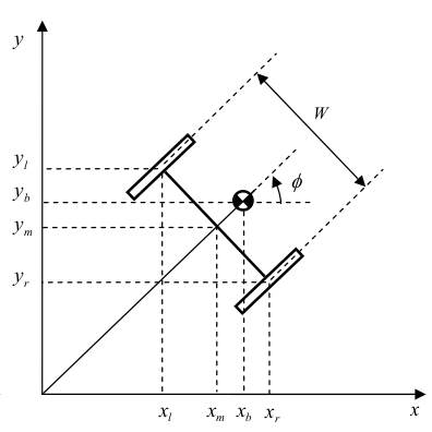
すべての質量の指定と慣性モーメントが図に示されています。 ロボットは1つのXOZ平面内でのみ移動すると想定されています。 システムの方程式のサイズを小さくするために、エンジンとホイールの慣性モーメントを個別に計算せずに、Segwayを一体型ブリックと見なします。
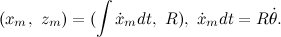
システムの重心の座標の方程式を書きます。

さて、ラグランジアンの方程式を冷静に書いてください。
計算を自動化するには、Maximaシンボリック計算システムとそのWxMaximaグラフィカル環境を使用します。 結果の式をコマンドラインに入力します。
V:expand( trigsimp( ((diff(integrate(R*diff(Theta(t),t),t)+L*sin(Psi(t)),t))^2+ (diff(R+L*cos(Psi(t)),t))^2)*M/2 +J2*(diff(Psi(t),t))^2/2-M*g*(R+L*cos(Psi(t))) ) ); tex(V);
コマンド\動詞| trigsimp | 三角式を簡略化するために使用され、\動詞|展開| ブラケットを開きます。 チーム\動詞| tex | 結果をtex形式に変換できます。これにより、数式をtexドキュメントまたは図面の形式で表示できます。

導関数をコンパクトな形式で記述し、次の方程式を取得します。

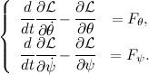
そして、次のようにラグランジュ方程式を書きます。
Maximaのプログラム:
U:expand(diff(diff(V,diff(Ttheta(t),t)),t)-diff(V,Theta(t))); Y:expand(diff(diff(V,diff(Psi(t),t)),t)-diff(V,Psi(t))); tex(U); tex(Y);
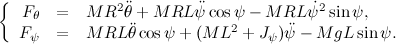
指定されたアクションを完了すると、以下を受け取ります。


次に、前の投稿
habrahabr.ru/post/178103の資料を使用して、セグウェイのエンジンの方程式を作成します。

巻線のインダクタンスは非常に小さいため、L = 0に設定します。

取得するもの:

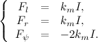
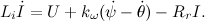
次に、モーメントの方程式を等式化し、左側に制御電圧を持つ要素のみを残します。
方程式を使用してフィードバック係数の行列を計算するために、結果のモデルを線形化します。 最初の顕著な制限、代替を使用します

そして

。 残りの非線形性も無視します。

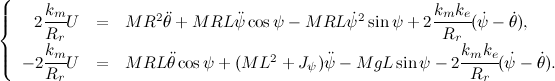
これで、以下を受け入れることにより、得られた方程式を行列形式で記録することができます。

:

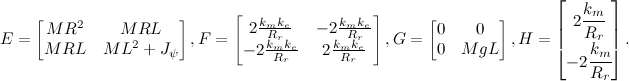
私たちにとってこれは珍しい形式なので、これらのマトリックスから、システムの状態マトリックスと制御マトリックスの2つのマトリックスを接着する必要があります。 これを行うには、状態変数を展開します

別の方程式を追加することにより:

これで、3次システムを受け取り、制御アクションに対するすべてのダイナミクスと反応がわかりました。 安定させるには、既知の安定したシステムを記述する行列を作成する必要があります。 このためにニュートン二項式を使用します

どこで

。 ここに

参照モデルの遷移時間の表形式の値、

ロボットのモデルの遷移時間。0.3秒に相当します。 参照モデルをコンパイルし、その固有値を計算します

を使用して、アッカーマンの公式のフィードバック係数を計算できます。


しかし、すべてが私たちが望むほどスムーズではありません。 わずか7 [V]ですが、制御電圧に制限を課していないため、得られた係数はおそらく機能していません。 これを修正するには、システムをシミュレートし、振り子とロボットの車輪の角速度の係数を減らす必要があります。

青線は、オーバーシュートと遷移時間の比率の観点から最も適しています。 その後、ロボットの作業プログラムを取得します。
#define GYRO_PORT IN_1 #define LEFT_MOTOR OUT_C #define RIGHT_MOTOR OUT_B #define BOTH_MOTORS OUT_BC #define WAIT_TIME 8.0 #define KGYROANGLE 0.487 #define KSPEED 0.024 #define KGYROSPEED 0.153 #define KPOS 0 task main(){ float time = WAIT_TIME * 0.001; float segway_angle = 0; float segway_speed; float wheel_angle = 0, last_wheel_angle; float wheel_speed; float max_voltage; int u; SetSensorHTGyro(GYRO_PORT); Wait(50); while(true) { max_voltage = BatteryLevel() / 1000; segway_speed = (SensorHTGyro(GYRO_PORT) + 2); segway_angle += segway_speed * time; last_wheel_angle = wheel_angle; wheel_angle = (MotorRotationCount(LEFT_MOTOR) + MotorRotationCount(RIGHT_MOTOR)) / 2; wheel_speed = (wheel_angle - last_wheel_angle) / time; u = KGYROANGLE * segway_angle + KSPEED * wheel_speed + KGYROSPEED * segway_speed + KPOS * wheel_angle; u = u * 100 / max_voltage; if (abs(u) > 100){ u = sign(u) * 100; } OnFwd(BOTH_MOTORS, u); Wait(WAIT_TIME); } }