最近のPCには、使いやすいインターフェイスがないという問題があります。 USBを使用するには大量の複雑なコードが必要ですが、UARTにはUSB-COMアダプターが必要です。 外部デバイスが単純な場合、インターフェースの開発はデバイス自体の開発よりも時間がかかる場合があります。 同時に、多くのデバイスには、オーディオデバイス用のアナログインターフェイスがあり、変更なしでデータを入力または出力できます。 STM32VLDISCOVERYボードからWindows XPを搭載したPCへのマイク入力によるデータ入力の例を次に示します。 インターフェイスは純粋にデジタルではなく、デジタルアナログです。 ボードからのデータは、コントローラーのDACを介して、異なる振幅の4つの矩形パルスのバッチで送信されます。 パルス繰り返し率は、ほとんどのサウンドカードの入力アンプの上限周波数(20 kHz)に対応しています。 パックの始まりは、幅が2倍のパルスでマークされます。 次の3つのパルスには、パルスの振幅に埋め込まれた情報が含まれています。 4ビット振幅コーディングのデータ転送速度は約45 kbit / sです。
ファームウェアSTM32VLDISCOVERYのコード:
#include "stm32f10x.h" #define DAC_DHR12RD_Address 0x40007420 #define BUF_SIZE 640 DAC_InitTypeDef DAC_InitStructure; DMA_InitTypeDef DMA_InitStructure; TIM_TimeBaseInitTypeDef TIM_TimeBaseStructure; uint32_t DualSine12bit[BUF_SIZE], Idx = 0, Idx2 = 0, Idx3 = 0, a1,a2,a3,a4, cc; int RR; double R; void RCC_Configuration(void) { RCC_AHBPeriphClockCmd(RCC_AHBPeriph_DMA1, ENABLE); RCC_APB2PeriphClockCmd(RCC_APB2Periph_GPIOA, ENABLE); RCC_APB1PeriphClockCmd(RCC_APB1Periph_DAC, ENABLE); RCC_APB1PeriphClockCmd(RCC_APB1Periph_TIM2, ENABLE); } void GPIO_Configuration(void) { GPIO_InitTypeDef GPIO_InitStructure; GPIO_InitStructure.GPIO_Pin = GPIO_Pin_4 | GPIO_Pin_5; GPIO_InitStructure.GPIO_Mode = GPIO_Mode_AIN; GPIO_Init(GPIOA, &GPIO_InitStructure); } void Timebase_Configuration(void) { TIM_TimeBaseStructInit(&TIM_TimeBaseStructure); TIM_TimeBaseStructure.TIM_Period = 0x120;
PCアプリケーションコード:
#include <stdlib.h> #include <stdio.h> #include <conio.h> #include <string.h> #include <fstream.h> #include <iomanip.h> #include <windows.h> #include <math.h> #include <vcl.h> #include <mmsystem.h> #include "mainF_dbl.h" #pragma hdrstop #pragma package(smart_init) #pragma resource "*.dfm" #define INP_BUFFER_SIZE 16384 #define SAMPLE_RATE 192000 TForm1 *Form1; static HWAVEIN hWaveIn = NULL; static WAVEHDR WaveHdr1, WaveHdr2; static WAVEFORMATEX waveformat ; static unsigned short Buffer1[INP_BUFFER_SIZE], Buffer2[INP_BUFFER_SIZE], saveBuffer[INP_BUFFER_SIZE]; static signed int RR, saveBuffer2[INP_BUFFER_SIZE]; static BOOL bEnding, bGraph, flag; BOOL bShutOff; long int RR_max, RR_min, LLL; int ix, iy, iz, k, kx, ky, m, kp ; void CALLBACK waveInProc1(HWAVEIN hwi, UINT uMsg, DWORD dwInstance, DWORD dwParam1, DWORD dwParam2) { switch(uMsg) { case WIM_OPEN: break; case WIM_DATA: CopyMemory (saveBuffer, ((PWAVEHDR) dwParam1)->lpData, ((PWAVEHDR) dwParam1)->dwBytesRecorded) ; if (bEnding){ waveInReset (hWaveIn); waveInClose (hWaveIn); return; } waveInAddBuffer (hwi, (PWAVEHDR) dwParam1, sizeof (WAVEHDR)) ; // Send out a new buffer break; case WIM_CLOSE: waveInUnprepareHeader (hWaveIn, &WaveHdr1, sizeof (WAVEHDR)) ; waveInUnprepareHeader (hWaveIn, &WaveHdr2, sizeof (WAVEHDR)) ; } } //xxxxxxxxxxxxxxxxxxxxxxxxxxxxxxxxxxxxxxxxxxxxxxxxxxxxxxx void __fastcall TForm1::startButtonClick(TObject *Sender) { bGraph=false; } //xxxxxxxxxxxxxxxxxxxxxxxxxxxxxxxxxxxxxxxxxxxxxxxxxxxxxxx void __fastcall TForm1::formDestroy(TObject *Sender) { bEnding=false; } //xxxxxxxxxxxxxxxxxxxxxxxxxxxxxxxxxxxxxxxxxxxxxxxxxxxxxxx void __fastcall TForm1::Button1Click(TObject *Sender) { bGraph=true; } //xxxxxxxxxxxxxxxxxxxxxxxxxxxxxxxxxxxxxxxxxxxxxxxxxxxxxxx __fastcall TForm1::TForm1(TComponent* Owner) : TForm(Owner) { waveformat.wFormatTag = WAVE_FORMAT_PCM ; waveformat.nChannels = 1; //2 ; waveformat.wBitsPerSample = 16 ; waveformat.nSamplesPerSec = SAMPLE_RATE ; waveformat.nBlockAlign = waveformat.nChannels * (waveformat.wBitsPerSample / 8); waveformat.nAvgBytesPerSec = waveformat.nBlockAlign * waveformat.nSamplesPerSec; waveformat.cbSize = 0 ; if (waveInOpen (&hWaveIn, WAVE_MAPPER, &waveformat, (DWORD)waveInProc1, 0, CALLBACK_FUNCTION)){ Application->MessageBox( "000000000","Error",MB_OK ); return; } bShutOff=false; // Set up headers and prepare them WaveHdr1.lpData = (BYTE *)Buffer1 ; WaveHdr1.dwBufferLength = INP_BUFFER_SIZE*2 ; // WaveHdr1.dwBytesRecorded = 0 ; WaveHdr1.dwUser = 0 ; WaveHdr1.dwFlags = 0 ; WaveHdr1.dwLoops = 1 ; WaveHdr1.lpNext = NULL ; WaveHdr1.reserved = 0 ; waveInPrepareHeader (hWaveIn, &WaveHdr1, sizeof (WAVEHDR)) ; WaveHdr2.lpData = (BYTE *)Buffer2 ; WaveHdr2.dwBufferLength = INP_BUFFER_SIZE*2 ; // WaveHdr2.dwBytesRecorded = 0 ; WaveHdr2.dwUser = 0 ; WaveHdr2.dwFlags = 0 ; WaveHdr2.dwLoops = 1 ; WaveHdr2.lpNext = NULL ; WaveHdr2.reserved = 0 ; waveInPrepareHeader (hWaveIn, &WaveHdr2, sizeof (WAVEHDR)) ; waveInAddBuffer (hWaveIn, &WaveHdr1, sizeof (WAVEHDR)) ; waveInAddBuffer (hWaveIn, &WaveHdr2, sizeof (WAVEHDR)) ; waveInStart (hWaveIn) ; bGraph=true; bEnding = FALSE; } void __fastcall TForm1::Timer1Timer(TObject *Sender) { if (bGraph){ kp++; if (kp>20){kp=0; Canvas->Brush->Color = Color; Canvas->FillRect(Rect(0,0,512,512));} k=0; m=0; RR_min=0; RR_max=0; kx=0; ky=0; for(int LLL=0; LLL<INP_BUFFER_SIZE; LLL++) { short)(saveBuffer[LL*2]); RR = (signed short)(saveBuffer[LLL]); if (RR > 0) { if(RR_max < RR) RR_max = RR; if((kx>6)&&(RR_min<30000)) { //&&(k==0)){ m=0; } if(RR_min < 0) { if (m==1) ix = -RR_min*16/1024; if (m==2) iy = -RR_min*16/1024; if (m==3) iz = -RR_min*4/512; } flag=false; kx=0; RR_min = 0; ky++; } if (RR < 0) { if(RR_min > RR) RR_min = RR; if (ky>6){ if (m==3) {Canvas->Brush->Color = TColor(RGB(iz, iz, iz)); Canvas->FillRect(Rect(ix,iy,ix+16,iy+16));} } if(!flag) m++; RR_max = 0; flag=true; ky=0; kx++; } } } }
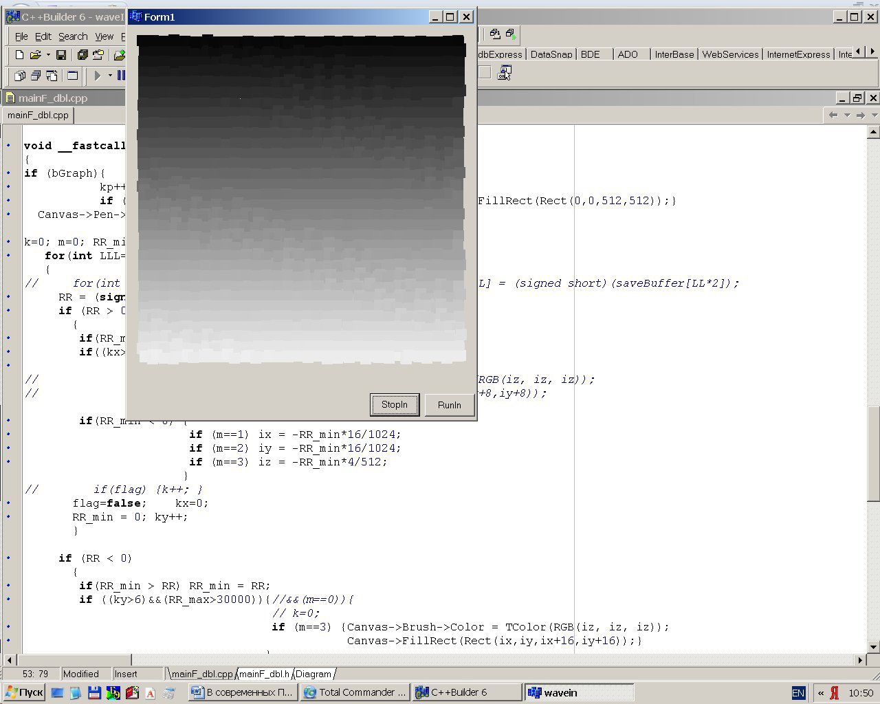
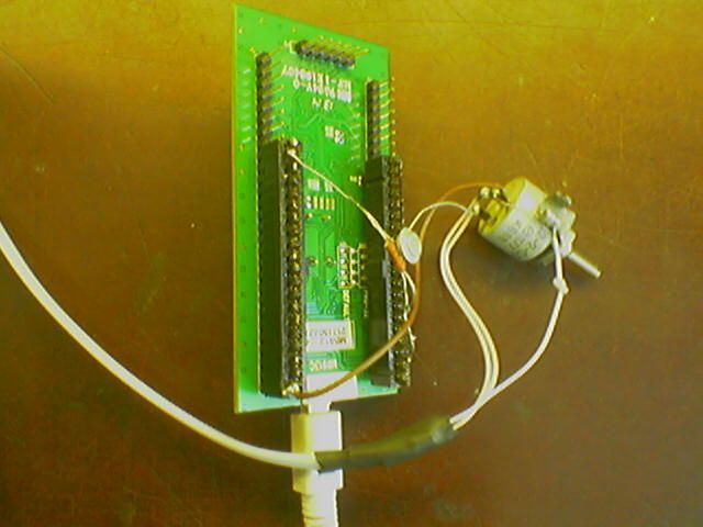
フォームには、「停止」と「実行」の2つのボタンと正方形のフィールドがあり、座標xとyの位置は最初の2つのパルスの振幅によって決まり、輝度は3番目の振幅によって決まります。 ボードは電話線で接続され、PC側にはモノ用の標準ジャックがあり、STM32VLDISCOVERY側にはPA.04ピンがエミッターフォロア(STM32VLDISCOVERYではDAC出力が高抵抗)とキャリブレーション用のディバイダー(可変抵抗器)を介して接続されます。
STM32VLDISCOVERYからのマイク入力を介してPCに送信されたテスト画像(上から下に正方形の輝度の勾配がある32x32正方形フィールド):